A quick and dirty 44 ft. Broadside Doublet / NorCal Doublet for portable operations

I first learned about The NorCal doublet from a YouTube video by my geology colleague and ham-radio instigator Tim (N7KOM). So last year I bought some ribbon cable, quickly made one, and it didn’t work: my radio couldn’t tune it. I suspect it was because my cable was 4 conductor and not 5 conductor.
Zoom to several months later and I started researching the type of antenna I wanted to install at my house. After a lot of advice, and research, I was very influenced by antenna wizard W4RNL‘s articles and hearty recommendation of multiple 44 ft (13.41 m) broadside doublets suspended from trees in my backyard. I have yet to build those particular ones, but in planning out that project I made the obvious connection that the NorCal doublet was this exact antenna, albeit with a less carefully constructed feedline.
Since learning this, I’ve been very intrigued about making a 44′ (13.41 m) doublet for portable operations. For the past year, I had been using resonant coax-fed dipoles, made out of speaker wire, for my POTA and SOTA activations. The have worked splendidly, but the RG-8U coax I have (don’t ask) is heavy (especially for SOTA), and I was wanting a true multiband antenna with a more consistent radiation pattern across bands. The 44′ (13.41 m) doublet would seem to do the trick.
I had initally wanted to make one out 450 Ohm ladder line and super thin Polystealth for weight and packability and use it for the Spring 2024 Trans-Atlantic Summit To Summit SOTA event. But, well, I didn’t order both in time from Davis RF. Something less polished and more kludgy would have to do.
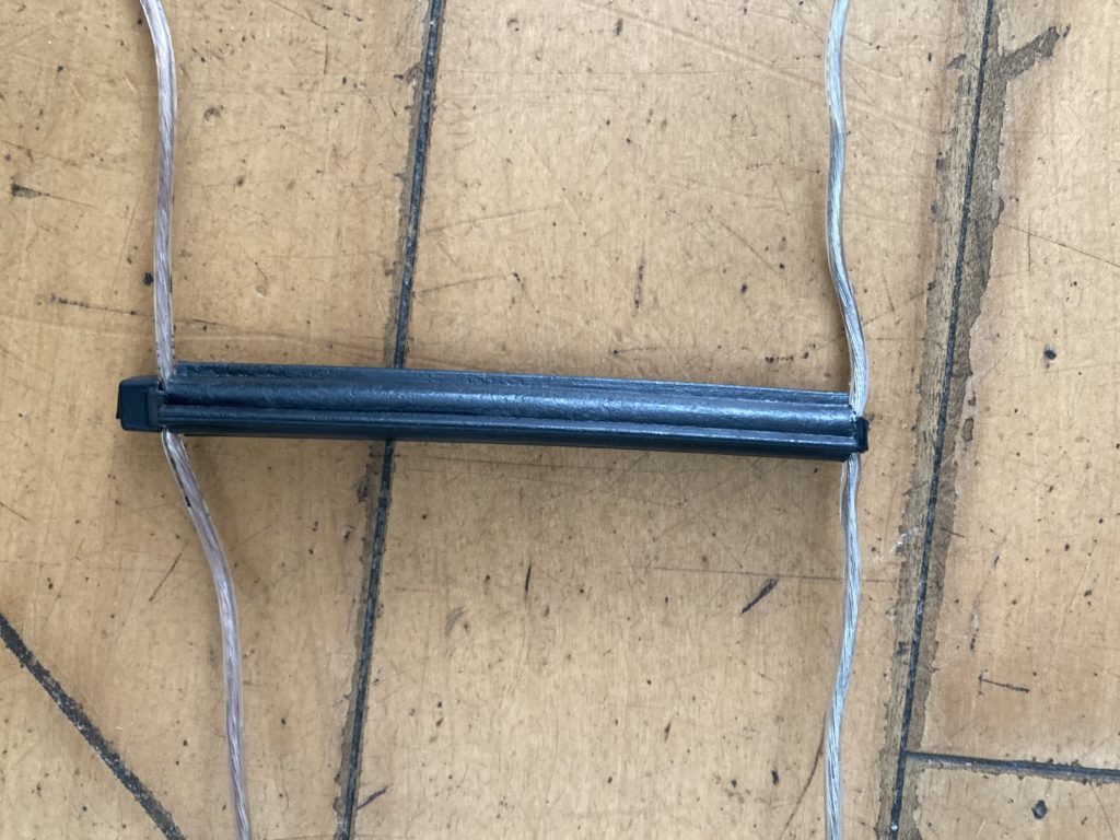
On the Friday afternoon before the event, I went to the hardware store and the local farmer’s cooperative and picked up some 18 AWG speaker wire and 4″ (10.16 cm) fin tube insulators to use as spacers. According to WRNL, this should give me a feedline impedance of about 600 Ohms, which according to him, many operators prefer for non-resonant dipoles of this sort as it’s a nice middle-ground between all the wildly different feedpoint impedances one encounters across the bands with this antenna. I measured out 50 ft (15.24 m) of speaker wire on my floor, marked off where the feedpoint would be with some sharpie and tape, and then split the insulation to make 2 conductors. I then used some 14″ (35.56 cm) zip ties, doubled up and threaded through the tube of insulator to fasten the insulators to the wire for the feedline, having anchored the speaker wire to a doorknob at one end of my house and pulling it taut. Putting the spacers every 16″ (40.64 cm), it was tedious work, but a lot faster than drilling holes and sliding them on. I had some extra insulators left over, so I put them in the middle of the feedline to make 8″ spacing between spacers for a short distance.

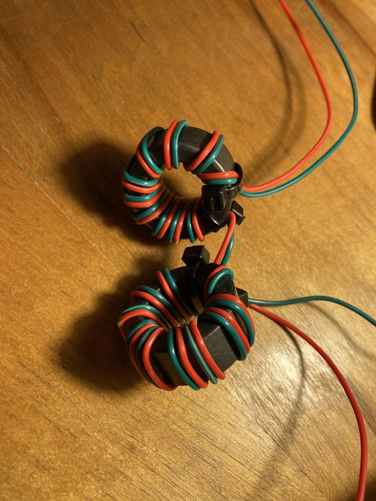
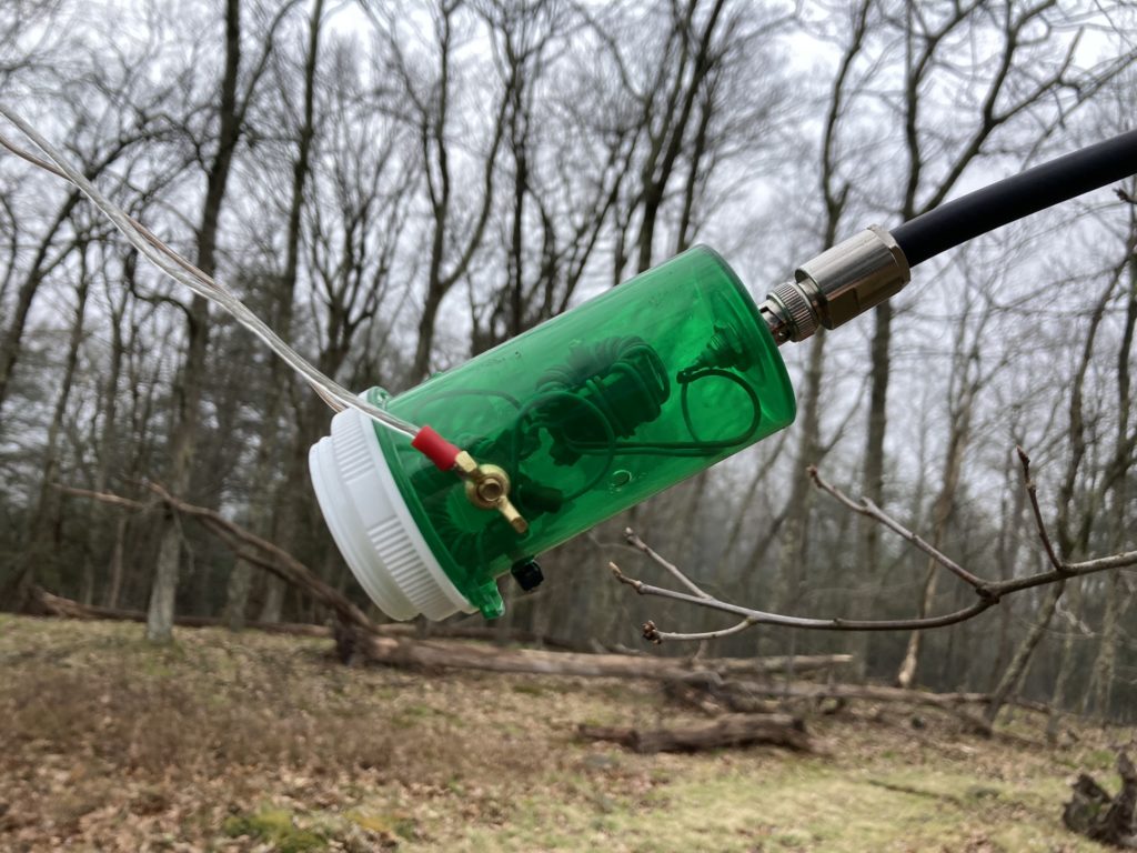
These sorts of antennas benefit big time from a 1:1 common mode choke. I spent a large portion of that evening making one of K9YC‘s bifilar, two-toroid designs, using two 1.25″ (3.18 cm) mix 31 toroids, with windings of conductors I separated from the aforementioned computer ribbon cable. A pill bottle from a local pharmacy made a convenient case, anchoring the toroids with some zip ties through holes to the sides of the bottle, and using a bulkhead BNC connector I had on hand for the connection to coax. I used some brass wingnuts and screws, in addition to ring terminals, for the connection to the feedline. I was tired, so kept having to solder and unsolder as I made basic spatial mistakes for how I was going to fit everything in the bottle: it took longer than constructing the antenna itself. In the end, it was hastily done, with sloppy spaced windings. It definitely won’t last forever, but it works and works OK.


When finally constructed (with spacers every 8″ which I added after publication of this post), it weighs in at 1.54 lbs (0.697 kg), which is considerably lighter than the 4.6 lbs (2.08 kg) weight of my 40m dipole and ~35 ft of DX Engineering RG-8U I had been bringing on activations before. I call that a win!
Parts List:
- 100 ft of 18 AWG speaker wire. I got mine at a certain nationwide hardware store chain.
- 4″ fin tube insulators: I got mine at the local farmer’s coop as they’re a great locally owned business and I try to support them. Tractor Supply carries these, but they are almost twice the price there as they are from online electric fence / ranch suppliers and significantly more than at the farmer’s coop.
- 14″ zip ties – I already had these on hand, but you could use 12 inch— they just have to be long enough that you have enough left over to thread around the wire, back through the insulator, and through the lock on the zip tie with enough left to pull tight. The trick with zip ties is making sure they’re thin enough that they still fit through the insulator when doubled. I read somewhere that the ones sold in hardware stores are overpriced and often not UV resistant, so I got mine online.
- One large pill bottle for the 1:1 bifilar Guanella-style choke housing
- Some 22 AWG wire I already had on hand for the toroid winding
- Two Fair-Rite Mix 31, 29mm outer-diameter, toroids from Mouser.com for a multiband RF feedline choke / 1:1 balun, constructed according to the 2018 choke cookbook linked above.
- Brass wingnuts and bolts, and ring terminals, I had on hand to connect the wound toroid to the feedline
- A BNC bulkhead connector to connect to coax going to the radio. I got this from a ham radio parts supplier.
- Small, 3″ zip ties to afix the toroids to the side of the pill bottle, to secure small loops of wire at the ends of the dipole legs to attached ropes to, etc.
- Solder.
I tested the antenna on the Trans Atlantic S2S SOTA event and a POTA activation a few days later. It performed admirably! See the blog posts on both of those, linked in the previous sentence. For the SOTA event, the tuner on the G-90 was able to load the antenna no trouble: it had low SWR on everything but the WARC bands (12 and 17), where the SWR was around 2-2.6: the antenna still seemed to perform efficiently though, and my signal was getting out quite far. 15m had variable SWR throughout the day, from 1.0 to 2.0. The antenna tuned up on 80m, but my waterfall was dead and I got no responses to my CQ. It was hard to know if it was band conditions, or if the antenna is too short to be an efficient radiator on that band: most folks say it shouldn’t and doesn’t work well at all on 80m (262.47 ft), but the NorCal doublet folks claim it works alright.
The POTA activation a few days later saw slightly different results: great SWR on 12m, but my radio was only putting out about 11 watts (from its normal 20), presumably due to its tuner finding an inefficient match. My signal was getting out broadside to the doublet, however, all the way out west to Colorado and Arizona. The 17m band had higher SWR again, with my signal mostly ending up about 45 degrees off the end of the doublet in the South, with some random QSOs in the Midwestern U.S., and one in Oregon with great signal reports. I want to chalk that up to band conditions, as the radiation pattern for this antenna on 17m is supposed to be a classic dipole donut.
A few weeks later I took it on another POTA activation, having added more spacers. This time, SWR was about 2ish on 17m and 20m. On 17m, my ALC was all over the place on USB in spite of my mic compression being set fairly low. Very unusual for this radio: the ALC almost never engages, and I don’t quite know was that was about Got great signal reports and audio reports regardless.
All in all, I’m very pleased with it, and it will definitely be my go-to portable antenna for when I’m operating in the woods. It’s much lighter than an equivalent feedline length in coax. This one takes up a lot of room, though: I currently pack it away in a 1-gallon zip-lock bag. I need to come up with a better bag, as I’ll be adding more spacers (16″ between spacers is too sparse: it’s easy for the feedline to twist over itself with the conductors’ insulation touching).
The only drawback is that things get difficult if one’s center support is less than 28 feet off the ground. With an open wire feedline it’s more important to keep it from resting on the ground: a challenge for this particular POTA activation. A solution to that may be to bring an extra length of paracord to suspend the feedline from another branch, halfway down the feedline’s length… or to set up an operating position far enough away from the branch so the feedline doesn’t touch the ground.
I will probably still order that 450 Ohm stranded window line from Davis RF, plus polystealth, for a more packable version. It will be interesting to see how the Xiegu G90’s internal tuner deals with that impedance.